PM CONTROLLER IN SERIES
Structure of the PM controller in series design
In the fig. a PM controller is shown in “series construction”, partially cut open. This controller is integrated in a hydraulic circuit diagram for a hydrostatic quill guide with 4 pockets. The PM regulator consists of the shown connection block of the pump pressure, a different number of regulator disks (in the figure three regulator disks). The advantage of this concept and of the regulator in series design is that all pocket pressures can be measured centrally at a branch of the connecting line regulator-hydrostatic pocket close to the regulator and that the regulator can be easily replaced, e.g. in case of contamination. The lines between the controller and the hydrostatic pockets should be kept as small as possible.
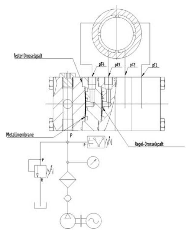
The following properties result from the design of the PM controller:
- As the flow through the first throttle point of the PM controller, just like the gaps of the hydrostatic pockets, is always laminar, the fluid flow through the controller and the hydrostatic pockets changes in the same way due to varying fluid viscosity, so that the stiffnesses and load capacities as well as the gap sizes and pocket pressures of the hydrostatic pockets are constant regardless of the fluid viscosity.
If the fluid viscosity changes, e.g. due to different fluid temperatures or by replacing the fluid (the permissible viscosity tolerance of an oil type is ± 10% according to DIN), the machine properties therefore hardly change. Only the required fluid flow and somewhat the damping properties are changed. - Since the fluid flow is controlled only by elastic deformation of the spring steel disc, i.e. there are no sliding movements, the PM controller operates without wear and hysteresis. Due to the low mass of the spring steel disk and high actuating forces, the PM controller is very fast, and the natural frequencies are many times higher than the excitation frequencies relevant in mechanical engineering. Since there are no sliding elements, the controller is also maintenance-free!
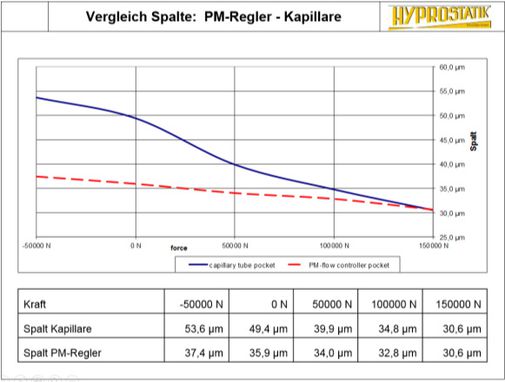
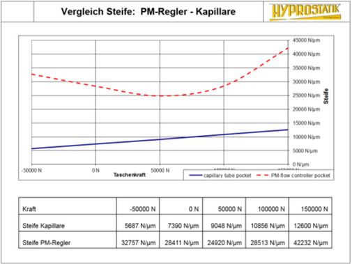
- At constant inlet pressure (= pump pressure), the PM controller feeds a likewise increasing fluid flow to the hydrostatic pocket when the load on a hydrostatic pocket increases, i.e. the pocket pressure and thus the outlet pressure at the controller increase. This results in approx. four times the stiffness (!) of solutions with capillaries.
The PM regulator thus exhibits the very atypical property of increasing fluid flow through the regulator as the differential pressure across the regulator decreases.
Advantages in all applications for guides:
- wear-free even at max. Load, thus no loss of precision with increasing service life
- Damping improved by orders of magnitude, resulting in significantly better workpiece surface and tool life
- No vibrations and fluctuations in friction as with rolling guides due to recirculating balls
- No reversal jump of the feed force when reversing the direction of movement
- virtually frictionless at low speeds no stick-slip effect
- Travel smaller than 0.1 µm possible
- The connection between the ports on the PM regulator is made by pipes, which should be as short as possible and their internal diameter should be such that the maximum oil velocity does not exceed 1 m/s.
The hydrostatic guidance is adapted to:
- Weights, machining and acceleration forces
- Maximum speed and acceleration as well as desired stiffness and optimum damping
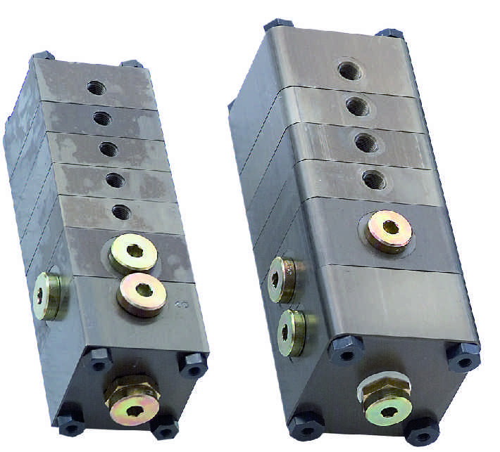
ADD-ON PM CONTROLLER
Advantages due to cultivation controller
Optimum dynamic conditions are achieved if the cable between the PM controller and the hydrostatic pockets is very short.
For this reason, the add-on controller was developed, which is used, for example, for hydrostatic lead screws and spindle bearings.
But it can also be used for guides.
These add-on controllers are usually attached to a flat ground surface of a machine part with hydrostatic pockets in such a way that the connection from the central connection of the add-on controller to the hydrostatic pocket is only achieved through a hole that is as short as possible.
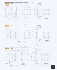
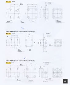
The oil supply from the pump to the attachment controller can also be made internally via the screw-on surface for the attachment controller (see illustration).
Alternatively, the oil can also be fed to the attachment controller externally via a threaded hole in the housing of the attachment controller by means of a pipe.


